One of the biggest problem today about the solar panels is the part after the solar cells, so the converter/ regulator. I wanted to write that for have the best performance with the solar cells for a smartphone / battery.
What do you need:
3x Solar Panels They are 6v/ 6w but in my opinion more about 5w. 3 because they can produce around 15v(5v x 3) so it’s the closet of the 12v required for the QC 3.0.
if you want to increase only the current you have to connect the (-) with the (-) and the (+) with the (+). But voltage will stay at 5v so the QC 3.0 will not work.
Part 3
Solder the (-) and (+) to the cigarette socket.
Part 4
Test it !
I use the new Xiaomi 20 000mAh power bank 2 (QC 3.0) with a low capacity (2/4 bar).
Around 10W !
When i made that picture the sun started to drew low, it was 20h14 and the panels were not super clean there was a little of dust on them. 20h14 is bad for the solar power, so it’s a really good result!
You can add more power by adding a solar panel in parrallele for exemple so you will need 6 panels (because we have to add a second panel for the 3 or the parrallel system will not works). But the QC is limited to 1.5A at 12v so it’s overpowered.
I’ve build today a 60Ah power bank with 12x 26650 Cells, they are really interesting for price/wh compared to the normal 18650, i paid them less than 4€ for 5 000 mAh cells (18wH), the bad side is the weight, more important than the best 18650 cells.
For the 26650 for each gram there is 52,4 mAh
For the 18650 (Panasonic 18650B 3500mAh), for each gram there is 73 mAh.
But the discharge rate is really good, it can handle 20A, and at 15A the capacity stay around 5Ah !
Review and tests of the Liitokal 26650 5,000mAh: link
So i think if you are looking for a portable(or not) power bank it’s surly the best choice, i will personaly use it with 4x5w solar panels, and i plan to add more cells in the futur for increase the capacity and power.
For the moment i use it with a 3S BMS 25A ( HX-3S-FL25A ):
Be careful with this BMS the B2(and not the B1) must be connected after the B+ ! Like here:
It’s limited 25A but because there are 12 Cells it can go up to 80A for continuous discharge and even up to 120A but the capacity will descrease to 3,5Ah for each cell. So it can produce around 888w(80A) and max 1322w (120A).
The Cells are sold around 24€ for 6 Cells, i got them for 22€ so with the bms it’s less than 50€.
If you want to use holders like me, they are really expensive but the quality is good(we also find the same one for the 18650 cheaper but I think it’s because the 18650 are very popular)
So the A20 will combine WIFI/GPRS/GSM/CAMERA, they are the same poeple who made the ESP8266 so maybe they will use this chip for the A20.
There is nothing in the datasheet about the wifi so idk why exacly they added the A20 name, and for the second page they said in chinese “to be updated” and “See full functional test board reference schematics”.
I’ve discovered the A7, an anwsome solution for have GPS and GPRS in the same chip thx to the great Andreas Spiess youtube channel:
But he he did not talk about the A6C module, maybe because the module was not annonced at this moment, let’s me tell you the avantages of this module:
Size: If you know the others cam solutions for the arduino and tiny devices, you surly know the ArduCam, and it’s a BIG module because the Arduino can’t be connected directly to the Camera or we need a lot connections so a big module like this one:
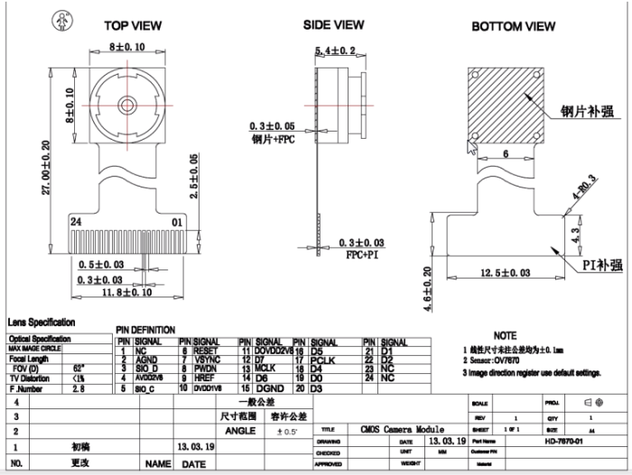
OV7670
The A6C has the same cam(OV7670) but it’s more smaller and we need just 2new connection for the Arduino, RX/TX just for the cam!
Price: Surly the important point because we can have smaller, better résolution, better gprs etc but much more expensive! I think for exemple to the Raspberry pi Zero and his high definition camera, normaly they cost around 25$ and with a good Gsm/gprs module around 50$. I also wanted to do a wireless camera with a Esp8266, it’s a cheap module but the cameras are really expensive, like this one: http://www.uctronics.com/arducam-2mp-v2-mini-camera-shield-with-esp8266-nano-esp-12f-evaluation-kits.html and i didn’t find a solution above 25$… But with the high price we have also better résolution, 2M against 0.3M max for the A6C but personaly i don’t know what can happen to a wireless module so i prefer a cheap one which do the basic job. His price is around 12$, with the camera which cost normaly around 3.5$. But the module is likely to cost less in the future because i’ve found only few sellers.
I think there is no better deal for a wireless Cam module at this moment, 12$ is a great price and it can be really interesting for the makers community which don’t want to spend more than 15$ for send a picture through a wireless module.
DEMO
Camera
AT Commands
AT+CAMSTART (Start the Cam and choose the resolution)
AT+CAMSTART=0 (QVGA: 320×240)
AT+CAMSTART=1 (VGA: 640×480)
AT+CAMSTART=2 (QQVGA: 160×120)
AT+CAMSTOP (Stop the camera)
AT+CAMCAP (Take a picture, the default format is .JPG)
AT+CAMRD (Read the content of the picture)
AT+CAMRD=fromaddr,toaddr;
AT+CAMREC (Not available for the moment)
AT+CAMCFG (Camera configuration)
AT+CAMCFG=mode,param
This is pure Reverso traduction because i don’t understand what they really say(in chinese):
0 indicates that the flash mode, the parameter is 0, Off, 1, 2 Open Automatically
1 indicates whether a night market, the parameter is 0, no night vision, 1 open the night vision
2 indicates that the image quality, parameters 0,1,2 //7,10,14,20
3 indicates that the image is rotated, the parameter is 0, indicating that will not rotate 1 rotate 90 degrees, 2 rotate 180 degree and 3 rotate 270 degree
4 The exposure parameters -2,-1,0,1,2
5 brightness, parameters -2,-1,0,1,2
6 white balance, parameter 0-auto,1-daylight,2- daylight (0x08),3-cloudy(0x09),4- (0x0a) tungsten lamps
If you want to test the tcp communication with the A6 Module you can follow this tutorial (but use the AT commands for the A6) BUT before, make sure the port is open, go in your router and create a “NAT”, choose the port you want(something like 747), internal and external(the same), for the device choose the internal IP of your computer.
You can check if the port his open with this website:
Good news for the A6, there is a simple way for TCP, i wrote in the previous article the long way with AT+CGACT=1,1 because AT+CIICR did not work for me but Simon f found the good order for use it, so i give you his code:
**Power Up**
AT+CSTT=”free”,””,””
OK
AT+CGDCONT=1,”IP”,”free”
OK
AT+CIICR
(we can wait a lot of time, if you see COMMAND NO RESPONSE! do nothing, this mess is send if a command don’t return a message after a while)
+CTZV:16/6/8, 1:33:8:8
+CGREG:5
OK
+CGREG:5
AT+CIPSTART=”TCP”,”speedtest.tele2.net”,21
+CDNSGIP:1,”speedtest.tele2.net”,”90.130.70.73″
OK
CONNECT OK
OK
AT+CIPCLOSE (If you want to close the actual tcp connection)
AT+CIPSHUT (If you want to stop the internet connection)
There is a new module, very cheap around 4$( Here). We can call/send sms and normaly connect to the website and surly use MQTT(i will explain why after). The good thing is we don’t need to spend more money for use it, there is a antenna and we just need to connect the speakers and a mic on the pins for use it. So it’s very close to the SIM800L(Here with bluetooth and rf in it!).
I recieved the module a week ago but i found nothing about the pinout, and the only things writed on it was 1, 12 and chineses things, maybe rx, tx ? No, with google translation i discovered it was like “made in shenzhen”… I tried different combination based on the videos, but nothing worked. On the official page they write for AT Commands “Included in the download link” so maybe the solution is in this file ? But i can’t find the link :(.
We find everything even the software used in the video!
A6 Gsm/GPRS Module Pinout
How use it:
Connect UART_TXD to RX of the FTDI
Connect UART_RXD to TX of the FTDI
Connect GND to the GND of the FTDI
Connect VCC5.0 To the PWR_KEY pin
Connect a Micro Usb for the power(with any smartphone charger)
After 4-5 second you can remove the connection between VCC5.0 and PWR_Key
You can open The arduino software, in tools select the good port(not COM1), open the serial monitor and choose 115200baud. Write “AT”, and if you see “OK” it works!
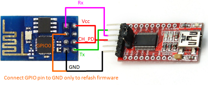
If you don’t know how exacly to do the connections, you can see how the Esp8266 works with a FTDI, it’s very close, for exemple:
The good new is the AT commands are very close to the Commands for others Gprs/Gsm modules like SIM800/SIM900 so it’s surly possible to use the same library.
I’ve noticed the CIPMUX command can’t be used, maybe it’s CMUX ?
How call ?
ATD+the phone number
For exemple: ATD0785957436
Push enter and you will recieve the call.
How send a message ?
AT+CMGF=1
AT+CMGS=”0785957436″ (It’s the phone number)
>(write the message here) (push Ctrl-Z and Enter, it doesn’t work in the Arduino Serial monitor but you can do it in SSCOM, the software in the Zip)
You can see all your previous message with:
AT+CMGR=1
for an another message change the number
AT+CMGR=2
AT+CMGR=10
AT+CMGR=12
AT+CMGR=18
AT+CMGR=24
Etc
And TCP/IP Connection ?
If i’m right this is the key for the MQTT connection to website etc so the most interesting part. I tried to do like in this page:
<= AT /** This should come back. SIM900 default is to echo back commands you enter **/
<= OK /** This string should tell you all is well**/
=>AT+CPIN? /**This is to check if SIM is unlocked. This sample assumes unlocked SIMs**/
<= +CPIN: READY /** If your response contains this, then it means SIM is unlocked and ready**/
=>AT+CREG? /**This checks if SIM is registered or not**/
<=+CREG: 0,1 /**This string in the response indicates SIM is registered**/
=>AT+CGATT? /**Check if GPRS is attached or not**/
<=+CGATT: 1 /**A response containing this string indicates GPRS is attached**/
//if you have CGATT:0, write CGATT=1 and even if you have an error check again
=>AT+CIPSHUT /**Reset the IP session if any**/
<=SHUT OK /**This string in the response represents all IP sessions shutdown.**/
//It Never works for me, i’ve +CME ERROR:50
=>AT+CIPSTATUS /**Check if the IP stack is initialized**/
<=STATE: IP INITIAL /**This string in the response indicates IP stack is initialized**/
=>AT+CIPMUX=0 /**To keep things simple, I’m setting up a single connection mode**/
//Not really important, i think for the A6 it’s AT+CMUX=0
<=OK /**This string indicates single connection mode set successfully at SIM 900**/
//I think it’s better to write that before:AT+CGDCONT=1,”IP”,”your_apn”
=>AT+CSTT= “APN”, “UNAME”, “PWD” /**Start the task, based on the SIM card you are using, you need to know the APN, username and password for your service provider**/
<= OK /**This response indicates task started successfully**/
=> AT+CIICR /**Now bring up the wireless. Please note, the response to this might take some time**/
<=OK /**This text in response string indicates wireless is up**/
//It never works for me
=>AT+CIFSR /**Get the local IP address. Some people say that this step is not required, but if I do not issue this, it was not working for my case. So I made this mandatory, no harm.**/
//It never works
<= xxx.xxx.xxx.xxx /**If previous command is successful, you should see an IP address in the response**/
//You can also use something like AT+CIPSTART=”TCP”,”www.google.fr”,”80″
<= CONNECT OK /**This string in the response indicates TCP connection established**/
=>AT+CIPSEND /**Request initiation of data sending (the request)**/
<= > /**The response should be the string “>” to indicate, type your data to send**/
=> xxxxxx /**Just type anything for now**/
=>#026 /**Now type the sequence #026. This tells the terminal.exe to send the hex code 0x1a (which is Ctrl+Z) to indicate end of data sending**/
<= xxxxxxxxxx /**You should get some response back from the server…it would generally be a complain that the request string was not valid…but that is a different subject…you have established the connection**/
/**To close the connection**/
=>AT+CIPSHUT /**Request shutting down of the current connections**/
<=SHUT OK /**Indicates shutdown successful**/
I think i can’t connect because my operator sends a message for activate internet on the phone, i need to install something after that so i can’t do it with this kind of module :/.
Let’s me know if it works for you!
Here an another page wich can be useful if you want to use the arduino and A6:
The commands seems to be the same exept for few of them, so it can works surly easily but i have not tried because i can’t do TCP connection, i will try it soon with an another sim card.
Power Consumption
I used a usb meter so the result are not great but it can give you an interesting overview:
Idk how much it is for the Sim800L, maybe the A6 is better for that.
If i change nothing, so i can call, send message etc, the power is around 0.06w/0.13w/0.20w and when i call it can reach 2W.
It’s for 5v so it’s around 0.03A
There is a low-power mode and they say it use only <1mA, but they don’t explain how to use it.